|
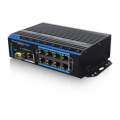
LS-UTP7208E-POE
Product: 8 Ports PoE Ethernet
Switch
Model: UTP7208E-POE
Description:
This switch is a kind of unmanaged switch with PoE function. It has one uplink
ethernet port and one optical port 1000Mbps; 8 100Mbps PoE ethernet ports
support af/at standard. This product is designed for HD IP Camera, enable these
devices to have power supply without connecting to the power socket. It makes
the connection of those devices far away from the power more flexible and
simplify wiring. This product integrate with optical port to realize perfect
integration between fiber optical transceiver and ethernet switch, solve the
problem of long distance transmission. It can be used in surveillance, network
engineering and so on.
|
|


|
|
|
|
|
|
1000Mbps optical port and Ethernet port supporting work at
same time; Fiber port support hot-plug SFP. |
PoE+ network port support IEEE802.3 af/at standard, support
distance up to 150m. |
Reset buttons of each port to solve the problem of terminal
device’s crash and disconnect problem. |
|
|
|
|
|
Redundant power design, power heat backup or raise
power consumption. |
Industrial standard product, fold metal outer
shell for heat dissipation without fan designed. |
Support Desktop, Din Rail and Wall
installation |
|
【Certification】
  
|
【Features】
1. Provide 8 10/100Mbps PoE ethernet ports, support power supply for the
network device meet IEEE802.3 af/at standard, Don’t worry about the damage of
devices which is not PoE.
2. PoE network port support IEEE802.3 af/at
standard, it can provide 30W consumption and power supply to the big consumption
infrared camera.
3. Provide 2 uplink ports, 1000Mbps optical port and
ethernet port; Uplink ethernet port can connect with NVR and other high
bandwidth device conveniently; Uplink optical port reserve SFP port for users to
select different performance SFP optical fiber module, conveniently solving the
problem of long distance transmission;
4. The switch and every PoE ethernet
ports have reset button for users to solve IP camera crash and others problem,
no need to pullout and plug network cables, which is convenient for system
maintenance; The reset button is on the bevel, convenient for users to operate
from multi-angle;
5. The transmission distance of uplink ethernet port can up
to 150m, break through the limit of 100m network cable;
6. Up to 1M Package
data cache, making more smooth of forwarding high-capacity data;
7. Up to 8K
for the MAC address, easily for system upgrade;
8. Support IEEE802.3X full
duplex flow control; support (Auto MDI/MDIX) function;
9. Redundance power
design, power heat backup or raise power consumption;
10. Industrial standard
product, fold metal outershell heat dissipation without fan designed;
11.
Installation fast, easily operation, convenient for wall, din rail and desktop
installation. |
【Specification】
|
Item |
Description |
|
Power |
Power Supply |
Power Adapter |
|
Power Adapter Voltage |
DC 48V-57V |
|
Consumption |
Default af standard<120W, at standard<240W (purchase power
adpater) |
|
Network Connector |
Network Port |
1~8 port:10/100Mbps PoE network port
UPLINK
port:10/100/1000Mbps network port
SFP:1000Mbps optical fiber SFP module
port |
|
Transmission Distance |
1~8 port:150m
UPLINK port: 150m
SFP: depend on the optical
module transmission performance |
|
Transmission Medium |
Cat5/5e/6 standard network cable |
|
PoE Protocol |
IEEE802.3af/at |
|
PoE Power Supply |
End-span |
|
PoE Power Consumption |
af≤15.4W (every port), at≤30W (every port) |
|
Network Switch |
Network Standard |
IEEE802.3 10BASE-T,IEEE802.3u 100BASE-TX, IEEE802.3ab
1000BASE-TX;
IEEE802.3z 1000-SX/LX;
IEEE802.3 X |
|
Switch way |
Store and forward |
|
Package data cache |
1M |
|
MAC address list |
8K |
|
LED Status Indicator |
Power indicator |
1 (red) |
|
Optical port LED indicator |
1 SPF port indicator (green) |
|
Uplink network port LED indicator |
1 (green on the RJ 45 socket) |
|
PoE network LED indicator |
8 PoE status indicator (yellow on the RJ 45 socket)
8 network
status indicator (green) |
|
Key Button |
PoE Reset Button |
8,corresponding with 1~8 port, PoE reset after press the
button |
|
Reset Button |
1, switch restart after press this button |
|
Protection |
Communication port Lightning protection |
4KV per: IEC61000-4-5 |
|
ESD |
1a contact discharge 3 level
1b air discharge 3
level
Per:IEC61000-4-2 |
|
Environmental |
Working temperature |
-10℃~55℃ |
|
Storage temperature |
-40℃~75℃ |
|
Humidity (non-condensing) |
0~95% |
|
Mechanical |
Dimension (L×W×H) |
159mm×110mm×46.5mm |
|
Material |
Aluminum |
|
Color |
Black |
|
Weight |
570g |
|
Stability |
MTBF |
>30000h |
【Interface】

Interface Introductions:
1) Front board with PoE ethernet port, the
yellow light on the RJ 45 socket left side is to indicate the PoE status, the
green light on the right side is to indicate network status; the yellow light
and green light on the Uplink network RJ 45 socket is to indicate network
working status; the LED on the SFP optical port left side is to indicate power
and optical port working status;
2) The left board and back board have a
DC48V~57V power input port respectively; default with a 120W power adapter, the
PoE output consumption of every port is 15W on the average , maximum output
consumption is 30W; if need each port output 30W, then need to purchase another
120W power adapter in addition. |
|

|
|
【Installation】
1) Please turn off the signal source and the device's power, installation
with power on may damage the device;
2) Use 8 network cables to connect 8 IP
cameras with POE switch's1~8PoE port;
3) Use another network cable or
(optical fiber) to connect PoE ethernet switch’s UPLINK port with NVR or
computer;
4) Connect PoE switch with power adapter;
5) Check if the
installation is correct and device is good, make sure all the connection is
reliable and power up the system;
6) Make sure every network device has power
supply and work normally. |
|
|
【SFP Optical Module Selection
Form】
|
ON |
Model |
Single Fiber/
Dual
Fiber |
Single-mode/
Multi-mode |
Bandwidth |
Distance |
Port |
Wavelength (nm)
|
|
1 |
UOF2102BS-20KM |
Dual Fiber |
Single-mode |
155Mbps |
20km |
LCPC |
1310 |
|
2 |
UOF2202BS-20KM |
Dual Fiber |
Single-mode |
1.25Gbps |
20km |
LCPC |
1310 |
|
3 |
UOF2101BS-T20KM |
Single Fiber |
Single-mode |
155Mbps |
20km |
LCPC |
1310/1550 |
|
4 |
UOF2101BS-R20KM |
Single Fiber |
Single-mode |
155Mbps |
20km |
LCPC |
1550/1310 |
|
5 |
UOF2201BS-T20KM |
Single Fiber |
Single-mode |
1.25Gbps |
20km |
LCPC |
1310/1550 |
|
6 |
UOF2201BS-R20KM |
Single Fiber |
Single-mode |
1.25Gbps |
20km |
LCPC |
1550/1310 | |
|
Naming Rule: UOF2a0bXY-Zc
a: Bandwidth, 1: 155M; 2:
1.25G; 3: 2.1G; 4: 4.25G; 5: 8G; 6: 10G
b: No. of Fiber, 1: Single Fiber, 2:
Dual Fiber
X: Optical Wave Length, A: 850nm; B: 1310nm; C: 1550nm
Y:
Single-mode OR Multi-mode, S: Single-mode; M: Multi-mode
Z:
Wavelength of Single Fiber, T: 13101550; R: 15501310
C: Distance, For
example: 20km, 40km,
60km | | |


 배송료
배송료