|
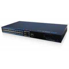
LS-UTP7224E-POE
Product: 24 Ports PoE Ethernet
Switch
Model: UTP7224E-POE
Description:
It is PoE switch which provides 24*100Mbps Ethernet ports, 2*1000Mbps optical
port and 2*1000Mbps uplink Ethernet port, support af/at standard. This product
is designed for HD IP camera, enable these devices to have power supply without
connecting to the power socket. It makes the connection of those devices far
away from the power and more flexible and simplify wiring. This product
integrate with optical port to realize perfect integration between fiber optical
transceiver and Ethernet switch, solve the problem of long distance
transmission. It can be used in surveillance, network engineering and so on.
|
|

|
|
【Certification】
  
|
【Features】
1. Provide 24*10/100Mbps PoE Ethernet ports, support power supply for the
network device meet IEEE802.3 af/at standard. Don't worry about the damage of
devices which is not PoE;
2. PoE network port support IEEE802.3 af/at
standard, it can provide 30W consumption, and power supply for the big
consumption infrared camera;
3. Provide 4 uplink ports, 2*1000Mbps optical
port and 2*1000Mbps ethernet port; uplink ethernet port can connect NVR and
other high bandwidth devices conveniently; uplink optical port reserve SFP port
for users to select different performance SFP optical fiber module, conveniently
solving the problem of long distance transmission;
4. The transmission
distance of uplink ethernet port can up to 150m, break through the limit of 100m
network cable;
5. High-speed data forwarding, very suitable for security
surveillance large flow video data forwarding;
6. Support IEEE802.3X full
duplex flow control; support (Auto MDI/MDIX) function;
7. Provide web
management software, can achieve realtime monitor of the working status of each
port, and also can control the power connection of each PoE port. It can be an
efficient solution for projects with complicated cabling;
8. Superior circuit
protection, up to 2KV shockproof;
9. Installation fast, easy operation,
convenient for wall, din rail and desktop installation. |
|
|
【Specification】
|
Item |
Description |
|
Power |
Power Supply |
Electric Power |
|
Power Adapter Voltage |
AC100V-240V |
|
Consumption |
430W, Max PoE output is 380W |
|
Network Connector |
Network Port |
1-24 Port: 10/100MbpsPOE network port
UPLINK Port:
10/100/1000Mbps network port
SFP: SFP optical fiber module port,
1000Mbps |
|
Transmission Distance |
1-24 port:150m
UPLINK port: 100m |
|
PoE Protocol |
IEEE802.3 af, IEEE802.3 at |
|
PoE Power Supply |
End-span |
|
PoE Power Consumption |
every port<30W, unit<380W |
|
Network Switch |
Network Standard |
IEEE802.3 10BASE-T, IEEE802.3u 100BASE-TX, IEEE802.3ab
1000BASE-T, IEEE802.3z 1000BASE-SXLX |
|
Package Data Cache |
9.6Mpps |
|
Switch Capacity |
12.8G |
|
Network Management |
VLAN Standard |
Based on Port VLAN |
|
LED Status Indicator |
Front Panel Indicator |
1 power status indicator (red), 24 network status indicator
(green), POE status indicator (red);
2 uplink Ethernet status |
|
Protection |
ESD |
1a contact discharge 3 level
1b air discharge 3
level
Per:IEC61000-4-2 |
|
Communication port Lightning protection |
3 level, Per: IEC61000-4-5 |
|
Environmental |
Working Temperature |
0℃-55℃ |
|
Storage Temperature |
-40℃-70℃ |
|
Humidity (non-condensing) |
0-95% |
|
Mechanical |
Dimension (L×W×H) |
442mm×217mm×44mm |
|
Material |
Aluminum |
|
Color |
Black |
|
Weight |
3.1kg |
|
Stability |
MTBF |
>30000h | |
|
【Interface】

|
| 【Application】 |
|

|
|
【Installation】
1) Please turn off the signal source and the device's power, installation
with power on may damage the device;
2) Use 24 Cat5/5e cables to connect PoE
IP camera with 1-24 Ethernet port (100Mbps) of 24 Ports Ethernet Switch;
3)
Use Cat5/5e cables (or fiber) to connect UPLINK of 24 Ports Ethernet Switch with
the device of NVR or computer etc;
4) Use Cat5/5e cables to connect Console
(PoE Web Software Control) of 24 Ports Ethernet Switch with device of control
terminal;
5) Connect AC power line of 24 Ports Ethernet Switch;
6) Check
if the installation is correct and device is good, make sure all the connection
is reliable and power for the system;
7) Make sure every network device has
power supply and work normally. |
|
|
【SFP Optical Module Selection
Form】
|
ON |
Model |
Single Fiber/
Dual
Fiber |
Single-mode/
Multi-mode |
Bandwidth |
Distance |
Port |
Wavelength (nm)
|
|
1 |
UOF2102BS-20KM |
Dual Fiber |
Single-mode |
155Mbps |
20km |
LCPC |
1310 |
|
2 |
UOF2202BS-20KM |
Dual Fiber |
Single-mode |
1.25Gbps |
20km |
LCPC |
1310 |
|
3 |
UOF2101BS-T20KM |
Single Fiber |
Single-mode |
155Mbps |
20km |
LCPC |
1310/1550 |
|
4 |
UOF2101BS-R20KM |
Single Fiber |
Single-mode |
155Mbps |
20km |
LCPC |
1550/1310 |
|
5 |
UOF2201BS-T20KM |
Single Fiber |
Single-mode |
1.25Gbps |
20km |
LCPC |
1310/1550 |
|
6 |
UOF2201BS-R20KM |
Single Fiber |
Single-mode |
1.25Gbps |
20km |
LCPC |
1550/1310 | |
|
Naming Rule: UOF2a0bXY-Zc
a: Bandwidth, 1: 155M; 2:
1.25G; 3: 2.1G; 4: 4.25G; 5: 8G; 6: 10G
b: No. of Fiber, 1: Single Fiber, 2:
Dual Fiber
X: Optical Wave Length, A: 850nm; B: 1310nm; C: 1550nm
Y:
Single-mode OR Multi-mode, S: Single-mode; M: Multi-mode
Z:
Wavelength of Single Fiber, T: 13101550; R: 15501310
C: Distance, For
example: 20km, 40km,
60km | | |


 배송료
배송료